Overview
In one sentence, VXLAN (RFC 7348) is a protocol for overlaying virtualized layer 2 networks over Layer 3 networks. In this post, I will first introduce some network basics for better understanding the concept of VXLAN. Then I will talk about what is VXLAN, why using VXLAN and the traffic flow in a VXLAN network.
VLAN (Virtual Local Area Network)
From the name we know that VXLAN is an extension of VLAN. Thus, let’s first figure out what is VLAN. Also because VLAN means virtual LAN, we’d better also learn something about LAN (What a recursive learning process!).
LAN
According to wikipedia:
A local area network (LAN) is a computer network that interconnects computers within a limited area such as a residence, school, laboratory, university campus or office building.
Basically LAN means a network of a bunch of interconnected computers. These computers form a single broadcast domain, which means if a computer sends a broadcast message on the LAN, it will be received by all other devices on the same LAN.
Then the question comes: how do we connect the computers so that each two of them can communicate? When you have only
two computers, you can just use one cable to connect them. When the third computer joins, you need 3 cables. So on and
so forth until there are n computers and you will have a mesh topology with n*(n-1)/2 links. Obviously this method
does not scale. Suppose only 10 people in your team but you have 45 cables connected to your laptop!
Hub (Layer 1 device)
A better idea is to connect a few computers to a hub or a repeater, which simply broadcasts any incoming data to every devices connected to it. The following graph shows how does a hub work.
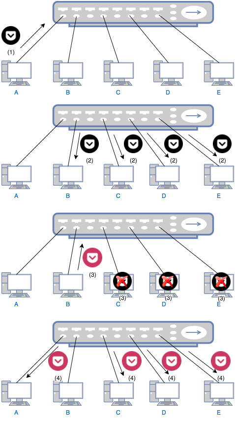
- Computer A wants to talk computer B and sends a message to the hub.
- The hub sends the packet to computer B, C, D and E.
- Only B replies to A through the hub. C, D and E just ignore A’s the message.
- The hub sends B’s reply to A, C, D and E. This time, only A handles the reply. C, D and E ignore the reply as in previous step.
There are two problems when using a hub: 1) Everybody can hear everything. The usage of a hub is similar to the case when your boss asks you to find Alice, you simply yell in the office, “ALICE, WHERE ARE YOU!”. This means you cannot share any secret with others. Of course you may claim that anyway you don’t tell secrets to your colleagues so this is not a problem. Then the second problem must concern you: 2) Collision. Obviously no two people can yell in the office at the same time; otherwise none of the two can be heard clearly. Similarly, if two computer tries to send data to the hub at the same time, collision will occur and one computer has to wait until the other one finishes. Suppose you have a talky colleague and you have to waste time waiting for him to finish his lengthy talk! To prevent the collision, a bridge or switch can be used.
Switch (Layer 2 device)
A switch is a bit smarter than a hub. When it receives a packet, it will only forward the packet to the designated receiver. Thus it needs to store the “address” of everybody in order to complete its job. The address for a computer is its MAC (Media Access Control) address. The switch needs to learn the MAC address to port mapping so that it can forward a packet to the correct port. Using above example again, this time when your boss asks you to find Alice, you first find Alice’s office number (MAC address), say 402. And you know that 402 is the second room on 4th floor. So you will just forward the boss’s message to that room (port). The traffic flow of communication using a switch is shown as follows:
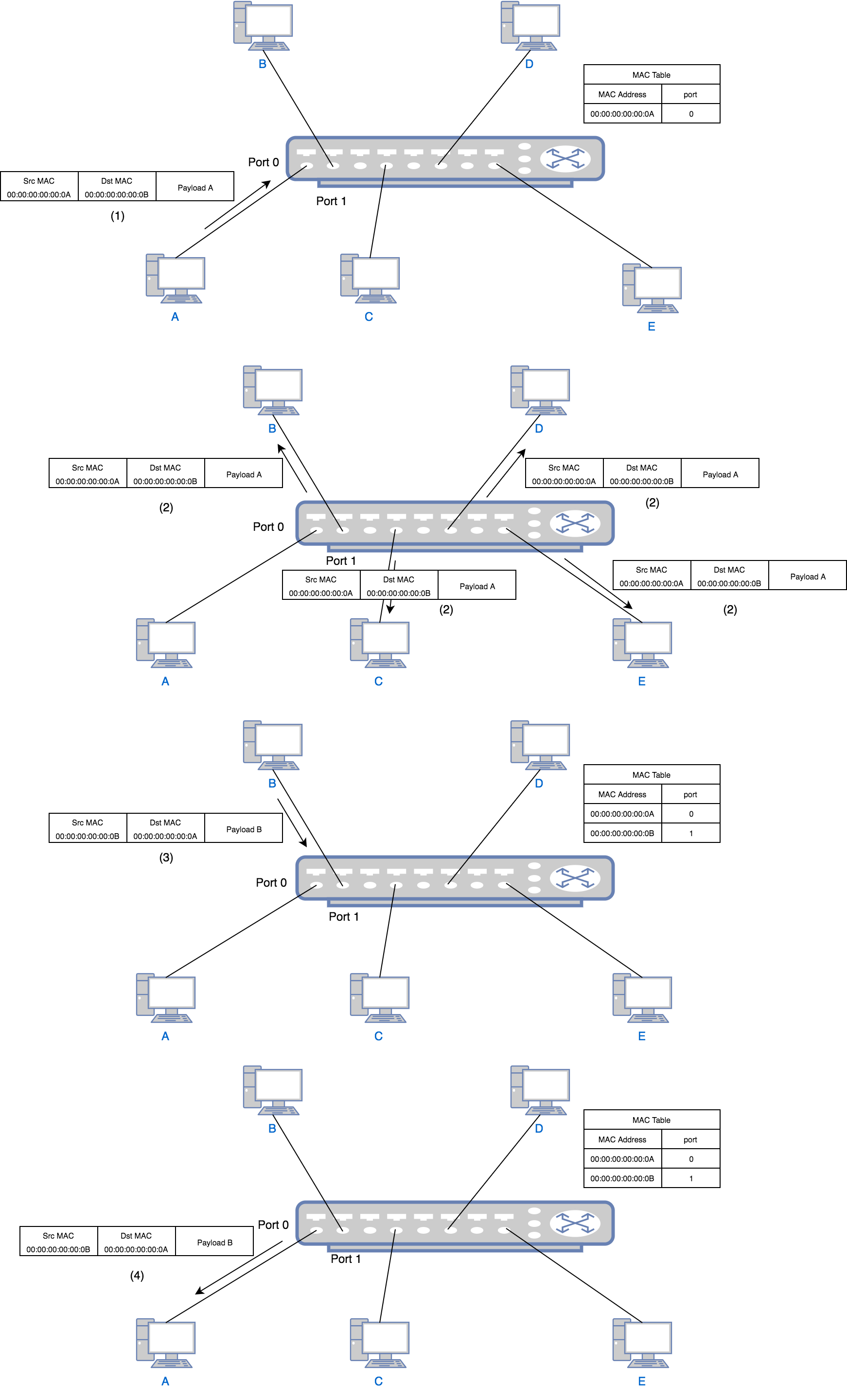
- Computer A wants to talk to computer B so it sends a packet with source address
00:00:00:00:00:0Aand destination address00:00:00:00:00:0Bto the switch port 0. The switch learns that port 0 is connected to a device with address00:00:00:00:00:0A, thus it writes00:00:00:00:00:0A-port 0to its MAC table. This is called source learning. - Because the MAC table currently does not contain the port mapping of address
00:00:00:00:00:0B, the switch still needs to send the packet to all ports except port 0. - B, C, D and E all receive the packet, but since the destination MAC is B’s MAC, C, D and E ignore it just as in the
hub example. Only B replies to A through the switch port 1. The reply has source address
00:00:00:00:00:0Band destination address00:00:00:00:00:0A. Similar to step 1, the switch learns that port 1 is connected to a device with address00:00:00:00:00:0B, thus it writes00:00:00:00:00:0B-port 1to its MAC table. - The switch find in the MAC table that the port of
00:00:00:00:00:0Ais port 0 so it just forwards the packet to port 0. For all following packets between A and B, the switch will just forward to specific port. No broadcast will happen after this point.
Collision Domain And Broadcast Domain
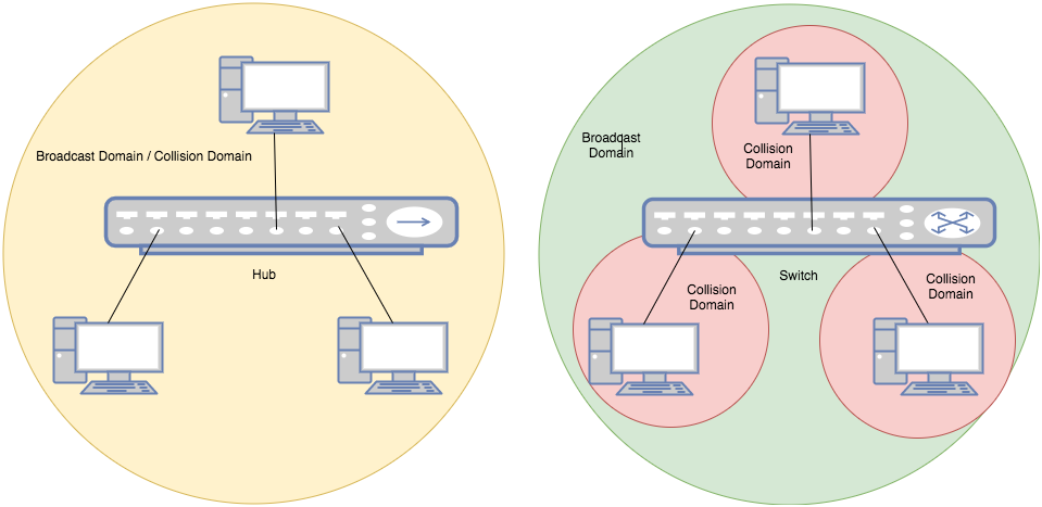
collision domain is where the collision happens. For instance, all ports in a hub form a collision domain because no two ports can send data at the same time otherwise collision happens. A switch is able to divide a collision domain, which means when devices are connected to a switch, each single port of the switch forms a collision domain.
broadcast domain, is where every node can reach each other by broadcast messages. In a hub, all ports also form a broadcast domain. So does a switch, as shown below:
Now we know that switch is the one that can divide a collision domain, then who can divide a broadcast domain? Before solving the question who, let’s first discuss why. Why we need to divide a broadcast domain? Similar to real life example, when a company becomes big, departments are no doubt necessary. In a single big office, when you announce to all engineers that their salary will be increased by 15%, the product managers will also hear that and become unhappy. But if engineer department has its own office, this problem can be solved. Besides, when you broadcast messages in a big office, you create noise for the people who don’t care about the messages. In network case, these are unnecessary traffics.
There are two ways to divide a broadcast domain, one is using a Layer 3 router, which we will not cover in this post; the other is VLAN, by which can solve the problem in Layer 2.
How VLAN works
From above we know that the purpose of VLAN is to divide a broadcast domain, which means dividing a bunch of computers into groups. Thus, the simplest way is to assign a tag to each group. As the name implies, this grouping is virtual. That is, for devices on a switch, even though physically they are in one broadcast domain, because of VLAN tags, logically they belong to different ones. For two devices belonging to different VLANs on a same switch, they need a router to talk to each other. And for two devices belonging to one VLAN but on different switches, they can communicate without a router if the two switches are connected by a trunk link. The following diagram shows the traffic flow in a VLAN:
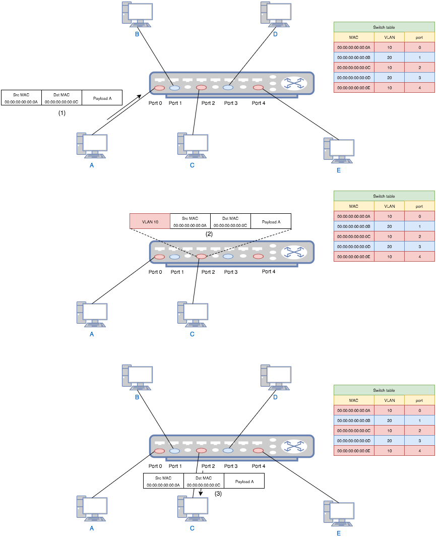
- Computer A (a VLAN-unaware device) sends a packet to switch port 0.
- The switch add a VLAN tag 10 to the packet and forward it to port 2.
- Port 2 checks the table and decides that this packet is allowed. Then it strips the VLAN tag and forwards the packet to computer C.
If A (belonging to VLAN 10) tries to send a packet to B (belonging to VLAN 20), then in step 3 the switch will simply drop the packet since port 2 is configured to only accept VLAN 20.
In real implementation, the VLAN tag is not the outer most header. And there are different types of VLANs. See Tagged, Untagged, and Native VLANs. In the diagram we put it in the front of the header so that we can think VLAN tag as an encapsulation, by which the partition of the network is achieved.
For more information about VLAN, see Network Warrior.
VXLAN
Why VXLAN?
After all those appertizers, finally we can come to the main course - VXLAN. From the name, we know that VXLAN is an
extension of VLAN. But why do we want to extend VLAN? One important reason is the limitation of VLAN - VLAN ID is a
12-bit number thus there are at most 4094 VLANs (000 and FFF are reserved so it is 2^12-2) in a network. However, for
a data center with tons of virtual machines, this number seems to be inadequate. Besides, the multi-tenant environment
puts more pressure on this number. VXLAN can address this problem by having a 24-bit VXLAN Network Identifier (VNI).
You may ask, does VXLAN just extend the tag from 12 bits to 24 bits? The answer is, no. VXLAN does more than that. If we see VLAN as a Layer 2 over layer 2 encapsulation, VXLAN is a more advanced layer 2 over Layer 3 encapsulation. Why can’t we just extend the number? This is limited by the Spanning Tree Protocol (STP) used in Layer 2 network in order to avoid loops in the network due to duplicate paths. For more information, see Why Spanning Tree Is Evil.
VTEP
Due to the encapsulation, VXLAN can be seen as a tunneling protocol. And the end point of the tunnel is called VXLAN Tunnel End Point (VTEP). A VTEP is responsible for encapsulation and decapsulation to make the underlay L2 network unaware of the overlay. For example, a hypervisor that hosts multiple VMs can act as a VTEP. It encapsulate a packet sent by a VM into VXLAN format and sends it through Layer 3 network. Then when the peer hypervisor receives the packet, it strips out the VXLAN header and sends the raw L2 packet to the destination VM. For those two VMs, they feel they are communicate over a Layer 2 network, unaware of the VXLAN overlay network. Think about VLAN, actually we can call a switch port a “VLAN Tunnel End Point”. Because it adds (encapsulates) and removes (decapsulates) VLAN tags and make the VLAN network transparent.
Each VTEP has two interfaces: One is a switch interface on the local LAN segment to support local endpoint communication through bridging, the other is an IP interface to the transport IP network. The IP interface has a unique IP address that identifies the VTEP device on the transport IP network. The VTEP device uses this IP address to encapsulate Ethernet frames and transmits the encapsulated packets to the transport network through the IP interface. A VTEP device also discovers the remote VTEPs for its VXLAN segments and learns remote MAC Address-to-VTEP mappings through its IP interface. The functional components of VTEPs and the logical topology that is created for Layer 2 connectivity across the transport IP network is shown as follows:
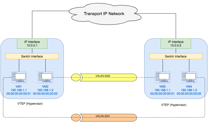
We can also see from the diagram that VMs in different VXLAN networks can have the same MAC address.
VXLAN Frame Format
Network is layered. The lower layer on the sender side always adds a outer header to the upper layer packet. While the same layer on the receiver side always strips out the outer header and then gives the result to upper layer. Because of this encapsulation and decapsulation, each layer feels that it talks to the same layer at peer directly, unaware of the existence of lower layers. Same concept also applies to VXLAN.
VXLAN encapsulation adds 50 bytes to the original L2 frame if no VLAN’s used or 54 bytes if the VXLAN endpoint is on a VLAN tagged transport network. For inner VLAN tag handling, see Inner VLAN Tag Handling. The whole frame after encapsulation is shown as follows:
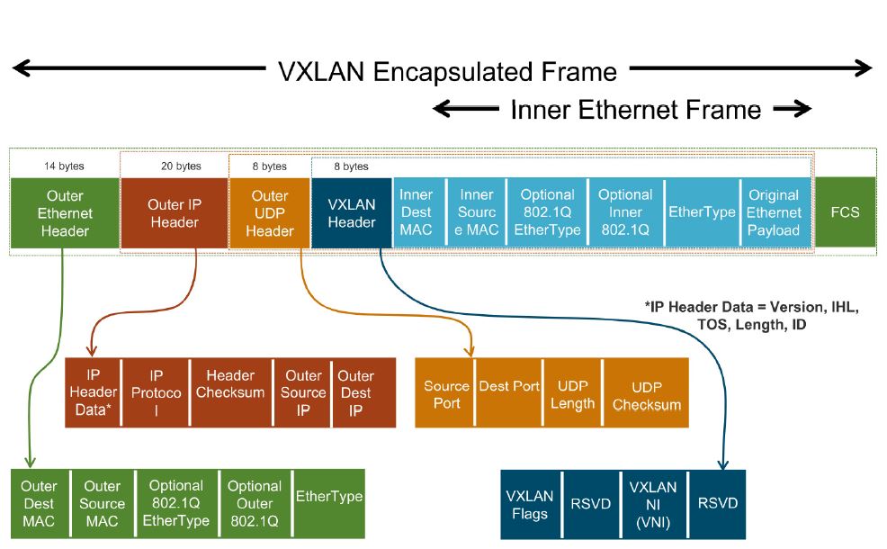
Image credit: VXLAN & LOGICAL SWITCH DEPLOYMENT. (This is a good blog post explaining VXLAN. But it focuses more on the VXLAN deployment on VMWare NSX).
As shown in the picture, the VXLAN header itself is 8 bytes, including a 24-bit VNI and a few reserved bits. It is then encapsulated in a UDP header. For detailed information about VXLAN format, see VXLAN Frame Format.
Traffic Flow in a VXLAN Network
Unicast VM-to-VM communication
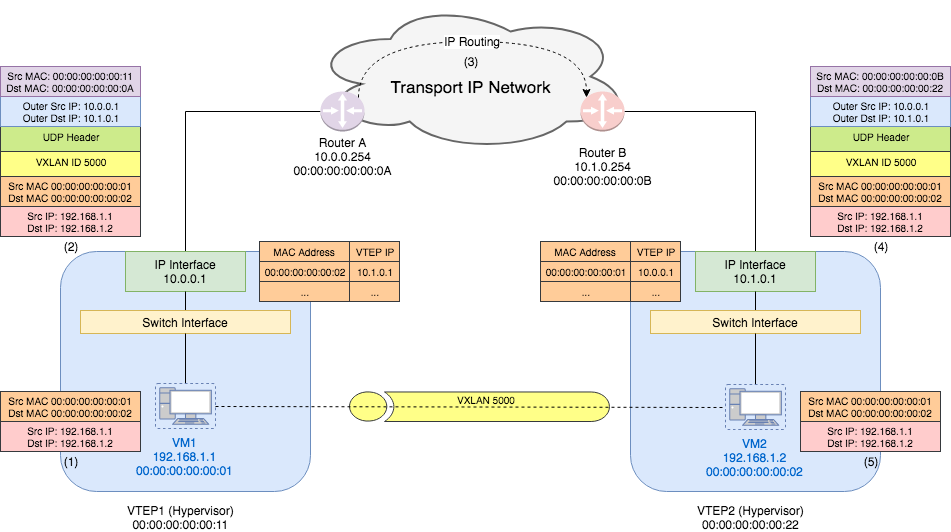
- VM1 sends a Ethernet frame with source MAC address
00:00:00:00:00:01(VM1’s MAC) and destination MAC address00:00:00:00:00:02(VM2’s MAC) to the VTEP1’s switch interface. VM1 and VM2 are in one VXLAN 5000. - VTEP1 checks its table and knows that VTEP of MAC address
00:00:00:00:00:02is10.1.0.1. Thus it adds a VXLAN header with VNI5000to the original packet. Next it adds a UDP header and then IP header with outer source IP10.0.0.1and outer destination IP10.1.0.1. Then it figures out from the routing table that the gateway for10.1.0.1is router A. Thus it adds an Ethernet header with the outer source MAC address00:00:00:00:00:11(VTEP1’s MAC address) and outer destination MAC address00:00:00:00:00:0A(router A’s MAC address). VTEP1 sends this encapsulated frame through its IP interface. - The router received the packet with source IP
10.0.0.1and destination IP10.1.0.1, It just sees it as a normal IP packet and take care of routing the packet to correct destination. This step is just as traditional Layer 3 network. - VTEP2 receives the packet from its gateway router B. Thus the frame it sees has outer source MAC address
00:00:00:00:00:0B(router B’s MAC address) and destination MAC address00:00:00:00:00:22(VTEP2’s MAC address). The outer IP addresses are same as what VTEP1 sends out. VTEP2 strips out the outer Ethernet, IP, UDP, and VXLAN headers and finally sees the inner Ethernet frame. - VTEP2 decides that the destination VM should be VM2. Thus it just forwards the original frame to VM2. For VM2, it only sees the original packet from VM1 and thinks they are in one L2 network.
(This example assumes that the MAC learning has been done. We will talk about MAC learning in a later post.)
Broadcast, Unknown-Unicast, and Multicast traffic
Similar to a VLAN network where a broadcast frame is sent to all switches carrying that VLAN, a VXLAN frame can also be sent to an IP multicast group on which that VXLAN overlay network is realized. This “broadcast by multicast group” scheme is proposed by RFC 7348 VXLAN. The actual implementation can also use multiple unicast to simulate broadcast. In this case, the VTEP needs to know the mapping between VNI and other VTEPs. This can be configured by a management layer. As far as I know, VMWare NSX supports unicast, multicast and hybrid mode for broadcast, unknown unicast, and multicast traffic (BUM traffic). See VXLAN & LOGICAL SWITCH DEPLOYMENT. Since I am not familiar with multicast, I will skip the example for BUM traffic flow. The basic idea is that all VTEPs in one VXLAN participate in one multicast group, through which BUM traffic in the VXLAN will be sent. I may update the details in a later post.
Reference
[1] RFC 7348 VXLAN
[2] VXLAN Overview: Cisco Nexus 9000 Series
Switches
[3] VXLAN & LOGICAL SWITCH DEPLOYMENT