Overview
In previous post, I described the concept of VXLAN and said it is heavily used in SDN (Software Defined Network). Although SDN is a relatively new concept, the support for virtual networking is not - Linux bridge has made it possible long before. It could be helpful to learn something about this predecessor before diving into SDN.
Linux Bridge is a kernel module that was first introduced in 2.2 kernel, then rewritten by Lennert Buytenhek. The code for bridging has been integrated into 2.4 and 2.6 kernel series. It implements a subset of the ANSI/IEEE 802.1d standard. In the end of the article, we will use a lab to learn the usage of Linux Bridge.
What Is a Bridge?
In the network course I had in school, only hub (Layer 1 device), switch (Layer 2 device) and router (Layer 3 device) are introduced and compared. All I know about bridge is, a bridge is a switch with only two ports. Maybe because nowadays bridges are not as widely used as switches and a switch is more advanced than a bridge, the switch is usually selected as the representative of Layer 2. It kind of makes sense - if iPhone X is available, why buying iPhone 8?
Bridge versus Switch
In some articles, the authors try their best to list differences between a bridge and a switch. For example, this wiki page shows 7 of them. Honestly, I am not quite convinced by those stated differences. My opinion is that people just try hard to make up differences to distinguish these two terms and refuse to admit that they actually have no major differences. This can be supported by the book Understanding Linux Network Internals in which the author says:
The terms bridge and switch can be used to refer to the same device. However, nowadays the term bridge is mainly used in the documentation (such as the IEEE specifications) that discusses how a bridge behaves and how the STP works. In contrast, references to the actual devices are usually made with the term switch.
The only cases where I have seen people referring to a bridge device using the term bridge is when the device is equipped with only two ports (and bridges with two ports are not that common nowadays). This is why I often define a switch informally as a multiport bridge. Unless you are familiar with the official IEEE documentation, you will probably use the term switch. I personally worked on bridging software for years, and as far as I can remember, I used the term bridge only when working on the documentation, never to refer to a device on any network setup.
Generally speaking, I can say that there is really no difference between a bridge and a switch.
Bridging VM Network
One use case of Linux bridge is bridging VM network. For example, suppose you have a physical Linux machine running as a KVM hypervisor that hosts some virtual machines. Now all the virtual machines want to access the external network but you have only one physical NIC (Network Interface Card). How can it happen? One solution is to use the Linux bridge. We will discuss how it works later. Before that, let’s first see how a bridge is used in the physical network.
Physical Bridge
Suppose in your office there is a small router with 2 ports - one WAN port and one LAN port. If you are the only one in the office then it is sufficient. However, there are two other colleagues also want to access the internet at same time. Thus you need the help of a bridge (or switch if you prefer. I will always use the term bridge hereafter) with at least 4 ports, as shown below:
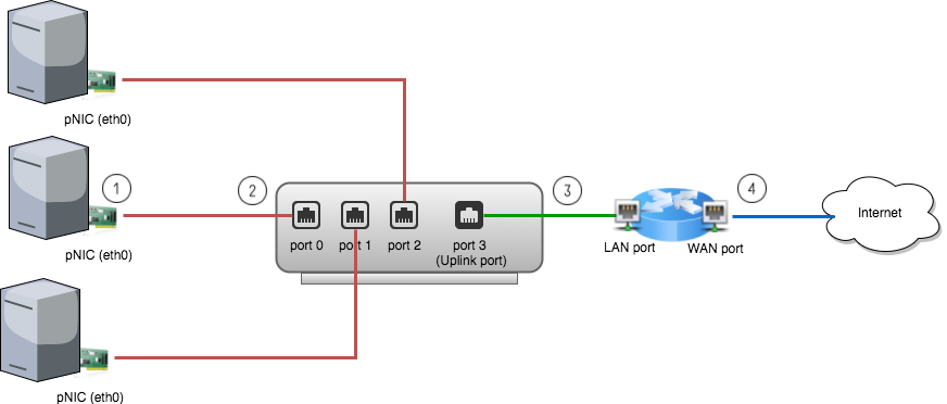
Following is the steps of how data flows from a physical machine to the internet: (Suppose ARP and MAC learning are all done and default gateway IP is set on the physical machines. For details of MAC learning, see previous post)
- A packet is sent to the pNIC (physical NIC) on the physical machine.
- The pNIC adds a L2 header to the packet with source address being the pNIC’s MAC and destination address being the router’s MAC and sends it to the bridge port 0.
- The bridge forwards the L2 frame received from port 0 to port 3, the uplink port.
- The router receives the packet and will route it to the final destination.
Linux Bridge (Virtual Bridge)
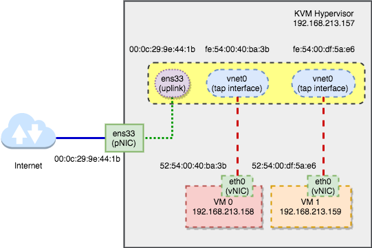
In the virtual world, nothing is new. All concepts we discuss above still apply. The only difference is, instead of a physical bridge with physical ports that you can see and touch, it now becomes a invisible and untouchable virtual bridge. Suppose in above network, one physical machine is a KVM hypervisor. Let’s enlarge it:
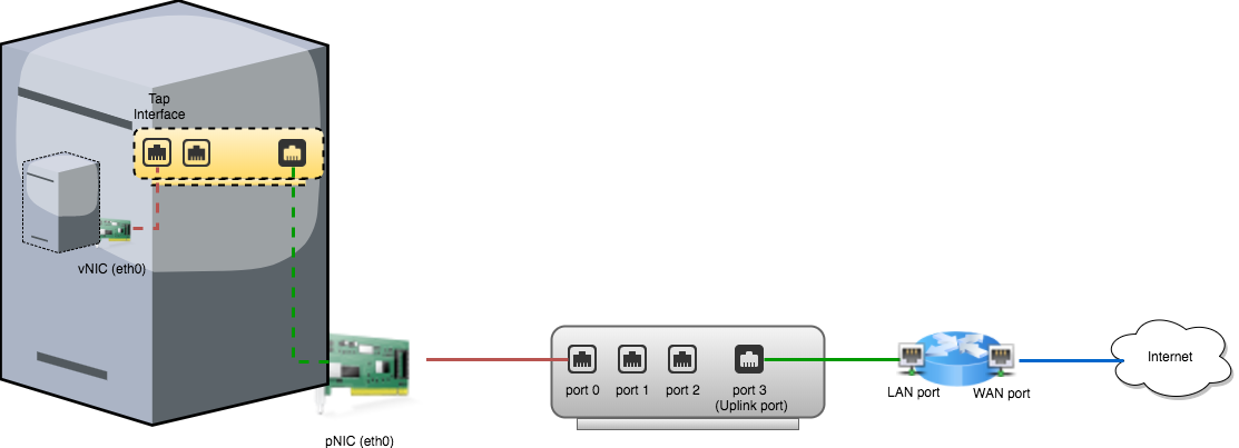
Obviously everything looks similar and now the pNIC on the physical machine now becomes the “router” of the virtual world. In order to distinguish between physical and virtual world, we call a NIC on a VM vNIC and call a virtual port on the Linux bridge a tap interface.
Lab
In this lab, I will use a KVM-enabled Linux machine. Honestly it is a virtual machine. But for the purpose of this lab, we just think it as a physical one. If possible, it is always better to use a true physical machine.
Note: If you are using VMWare fusion or VMWare workstation, go to “Settings” -> “Processors & Memory” -> “Advanced options” -> Check “Enable hypervisor applications in this virtual machine” to enable nested virtualization.
Step 1 - Set Up a Bridge
First, we have to create a bridge. There are two ways to do it - one is using
distribution-specific scripts; the other is manual configuration. See “Public
Bridge” section in this
instruction. For simplicity, I will
use the first method. However, the second one worth trying since it shows how a
bridge is created and how the ports are added to it step by step. Since my
hypervisor is an ubuntu machine, I need to modify the /etc/network/interfaces
file and restart the network:
$ cat /etc/network/interfaces
auto lo
iface lo inet loopback

auto br0
iface br0 inet dhcp
    bridge_ports    ens33
    bridge_stp      off
    bridge_maxwait  0
    bridge_fd       0
$ sudo /etc/init.d/networking restart
Note: My pNIC interface name is ens33. Typically for a physical machine,
it should be eth0.
After restart the network, the bridge br0 should get the IP address (through
DHCP) while the physical ens33 is left without an IP address. As shown below:
$ brctl show
bridge      name bridge id      STP enabled interfaces
br0         8000.000c299e441b   no          ens33

$ ifconfig br0
br0       Link encap:Ethernet  HWaddr 00:0c:29:9e:44:1b
          inet addr:192.168.213.157  Bcast:192.168.213.255  Mask:255.255.255.0
          inet6 addr: fe80::20c:29ff:fe9e:441b/64 Scope:Link
          UP BROADCAST RUNNING MULTICAST  MTU:1500  Metric:1
          RX packets:484968 errors:0 dropped:0 overruns:0 frame:0
          TX packets:45096 errors:0 dropped:0 overruns:0 carrier:0
          collisions:0 txqueuelen:1000
          RX bytes:678890117 (678.8 MB)  TX bytes:3433367 (3.4 MB)

$ ifconfig ens33
ens33     Link encap:Ethernet  HWaddr 00:0c:29:9e:44:1b
          inet6 addr: fe80::20c:29ff:fe9e:441b/64 Scope:Link
          UP BROADCAST RUNNING MULTICAST  MTU:1500  Metric:1
          RX packets:528979 errors:0 dropped:0 overruns:0 frame:0
          TX packets:56503 errors:0 dropped:0 overruns:0 carrier:0
          collisions:0 txqueuelen:1000
          RX bytes:730632857 (730.6 MB)  TX bytes:4201577 (4.2 MB)
Notice that the interface br0 and ens33 have the same MAC address.
Because currently ens33 represents not only the pNIC but also the uplink port
of the bridge. This implies the green dot line in above
graph.
Step 2 - Connect VMs
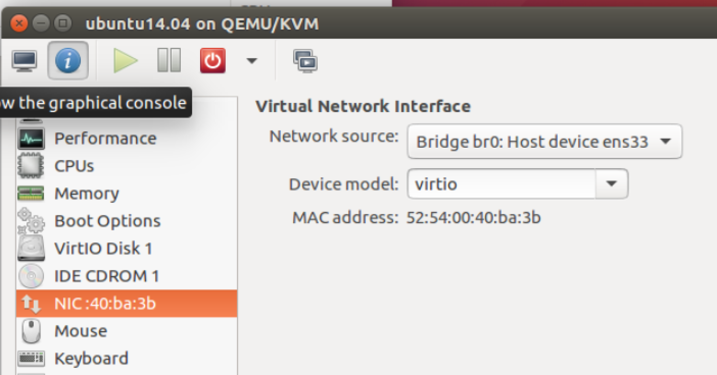
Second, start a VM and set it to connect to the bridge br0. I am using
Virtual Machine Manager, which is a GUI application
for libvirt. The setting is as follows:
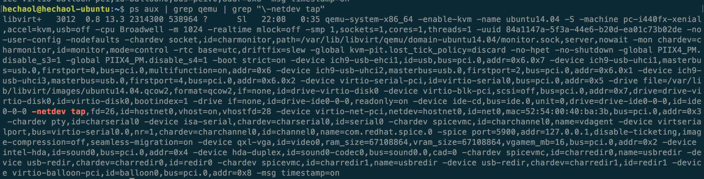
Or if you prefer to start a VM with command line, then just add the parameter
-netdev tap. This will connect the vNIC to the tap interface on the bridge.
For example, the command libvirt uses to start the VM is as follows:
After starting the VM, the bridge should now have two interfaces:
$ brctl show
bridge      name bridge id      STP enabled interfaces
br0         8000.000c299e441b   no          ens33
                                            vnet0
The interface vnet0 is a tap interface created by libvirt.
$ ifconfig vnet0
vnet0     Link encap:Ethernet  HWaddr fe:54:00:40:ba:3b
          UP BROADCAST RUNNING MULTICAST  MTU:1500  Metric:1
          RX packets:600 errors:0 dropped:0 overruns:0 frame:0
          TX packets:991 errors:0 dropped:0 overruns:0 carrier:0
          collisions:0 txqueuelen:1000
          RX bytes:43098 (43.0 KB)  TX bytes:1436545 (1.4 MB)
Now the VM should be able to connect to the Internet through this bridged network. On the VM, run:
$ ifconfig eth0
eth0      Link encap:Ethernet  HWaddr 52:54:00:40:ba:3b
          inet addr:192.168.213.158  Bcast:192.168.213.255  Mask:255.255.255.0
          inet6 addr: fe80::5054:ff:fe40:ba3b/64 Scope:Link
          UP BROADCAST RUNNING MULTICAST  MTU:1500  Metric:1
          RX packets:982 errors:0 dropped:0 overruns:0 frame:0
          TX packets:591 errors:0 dropped:0 overruns:0 carrier:0
          collisions:0 txqueuelen:1000
          RX bytes:1435849 (1.4 MB)  TX bytes:41244 (41.2 KB)
The VM gets an IP address in the same subnet of the physical host. Notice
that the vNIC’s MAC address 52:54:00:40:ba:3b looks similar to the tap
interface’s MAC address fe:54:00:40:ba:3b - only the first byte is different.
I guess this is how KVM represents the connection between vNIC and the tap
interface.
I will add another VM before next step. After that, libvirt should create one
more tap interface vnet1. Now our topology looks like:
Current bridge interfaces:
$ brctl show br0
bridge name bridge id           STP enabled interfaces
br0         8000.000c299e441b   no          ens33
                                            vnet0
                                            vnet1
Step 3 - Capture Packets
In this step we will use Wireshark to capture packets on each interface. Before that, let’s look at the bridge’s initial MAC table:
Initial MAC Table
$ brctl showmacs br0
port no mac addr            is local?   ageing timer
  1     00:0c:29:9e:44:1b   yes           0.00
  1     00:0c:29:9e:44:1b   yes           0.00
  2     fe:54:00:40:ba:3b   yes           0.00
  2     fe:54:00:40:ba:3b   yes           0.00
  3     fe:54:00:df:5a:e6   yes           0.00
  3     fe:54:00:df:5a:e6   yes           0.00
Note: I have no idea why the MAC table shows duplicate entries for each local port. Here somebody said it might be a bug. This person asked same question but was not answered. Please do let me know if you have the answer!
Suppose no duplication exists, then this table shows the initial state of the
MAC table before any traffic goes through the bridge. The bridge only has local
MAC addresses of its ports. From ifconfig results in step 2, we know
that port 1 is br0(ens33), port 2 is vnet0 and port 3 is vnet1.
Ping from VM0 to VM1
Next we start Wireshark on the hypervisor and capture packets on br0, ens33,
vnet0 and vnet1. Then let VM0 (192.168.213.158) ping VM1 (192.168.213.159).
$ ping -c 1 192.168.213.159
PING 192.168.213.159 (192.168.213.159) 56(84) bytes of data.
64 bytes from 192.168.213.159: icmp_seq=1 ttl=64 time=0.662 ms

--- 192.168.213.159 ping statistics ---
1 packets transmitted, 1 received, 0% packet loss, time 0ms
rtt min/avg/max/mdev = 0.662/0.662/0.662/0.000 ms
The result in Wireshark:
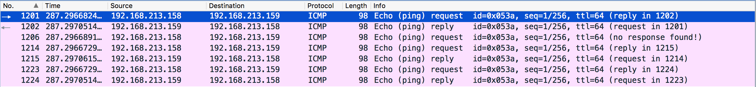
We only sent one ICMP request, why there are so many of them? Let’s analyze them packet by packet. We can add one column that shows the interface on which the packet is captured and order the result by time:
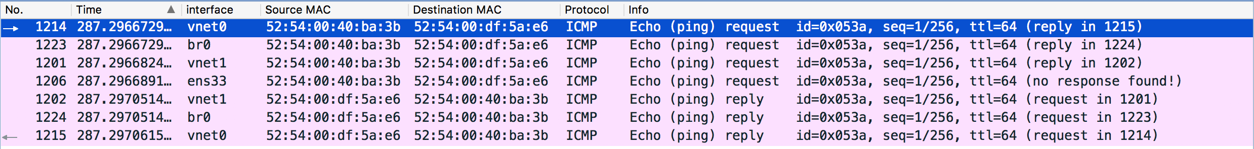
- The first packet goes from
vNIC0to bridge tap interfacevnet0. - The bridge interface
br0receives the packet and adds an entry to the MAC table with port 1, MAC address52:54:00:40:ba:3band “is local” no. This is called source MAC learning. (We can see this packet only because the Linux bridge exists as an interfacebr0. For a physical bridge, there is no such packet that can be captured). Since the bridge currently does not have the port mapping of the destination MAC address, it has no idea where to forward the packet. Thus it forwards it to every port except for the source portvnet0. - Port
vnet1receives the packet and will forward it tovNIC1. - Port
ens33receives the packet and will ignore it because the destination MAC address doesn’t match its own MAC. In Wireshark it also shows “no response found!”. If there are more VMs in this network, we should be able to see more requests with no response. vNIC1receives the packet and replies tovnet1, which will forward it to the bridge interfacebr0.- The bridge interface
br0receives the reply packet. This time it knows the destination MAC is mapped tovnet0so it will just forward the packet there. - Port
vnet0receives the reply and will forward it tovNIC0.
Now let’s see the MAC table (Duplication removed):
$ brctl showmacs br0
port no mac addr        is local?   ageing timer
  1 00:0c:29:9e:44:1b   yes        0.00
  2 52:54:00:40:ba:3b   no       183.20
  3 52:54:00:df:5a:e6   no       183.20
  2 fe:54:00:40:ba:3b   yes        0.00
  3 fe:54:00:df:5a:e6   yes        0.00
We can see that two MAC entires are added and both of them are remote MACs. Port
2 (vnet0) is associated with 52:54:00:40:ba:3b (VM0) and Port 3 (vnet1) is
associated with 52:54:00:df:5a:e6 (VM1). That means any packet sent to VM0
will be forwarded to port 2 and any packet sent to VM1 will be forwarded to port
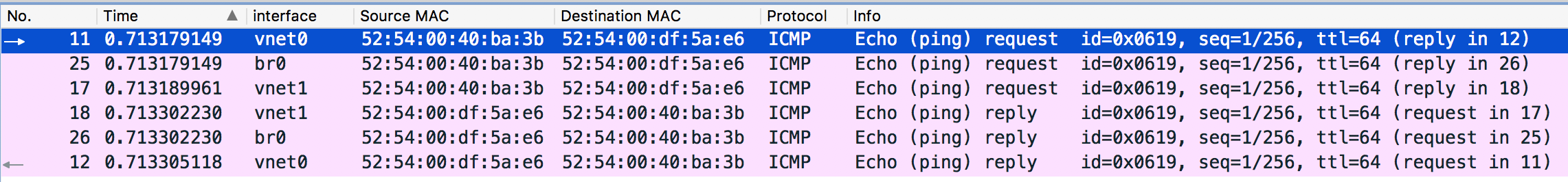
- If we ping again, we should only see 6 packets instead of 7 - the packet sent
to
ens33should not appear any more. Shown as follows:
Ping from a VM to the Internet
This time we ping from a VM to the Internet and again use Wireshark to capture the packets.
$ ping -c 1 hechao.li
PING hechao.li (192.30.252.153) 56(84) bytes of data.
64 bytes from lb-192-30-252-153-iad.github.com (192.30.252.153): icmp_seq=1
ttl=128 time=444 ms

--- hechao.li ping statistics ---
1 packets transmitted, 1 received, 0% packet loss, time 0ms
rtt min/avg/max/mdev = 444.605/444.605/444.605/0.000 ms

I will leave the analysis to the reader.
Note:
- ARP and DNS packets are filtered out.
- Notice that packet 336 and packet 340 are received at the same time so don’t be confused by the order shown in Wireshark.
- Ignore the “no response found!” info. It is a known bug of Wireshark.
Conclusion
In this post, we discussed what is a Linux Bridge and compared it with a physical bridge. We also did an experiment in which Wireshark is used to capture packets in a KVM bridged network. Analysis of the captured packets matches the theory and helps us understand how exactly the bridge works.
Reference
[1] Understanding Linux Network Internals by Christian Benvenuti
[2] Linux Bridge and Virtual
Networking
[3] Linux BRIDGE-STP-HOWTO
[4] Tap Interfaces and Linux Bridge
[5] Configuring Guest Networking