Overview
We talked about what is a bridge (switch) and how it works here and here. However, we only saw the topology in which one bridge is used to merge LANs. In real life, redundancy is always necessary in order to provide high availability. For example, instead of using only one link between two bridges, we can use two links so that the traffic won’t be affected even if one of them goes down. But this configuration also creates a loop in the topology which can severely affects the network. The Spanning Tree Protocol (STP) is used to make any topology loop-free. In this article, we will see how loops in a topology can be harmful and how STP solves the problem.
Problems of Loops in a Topology
Broadcast Storm
Suppose we have the following topology where two links exist between two bridges.
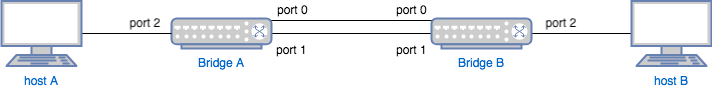
Obviously, there is a loop between two bridges. When Host A sends out a broadcast packet, what will happen is:
- The broadcast packet sent out by Host A is received by Bridge A port 2.
- Since this is a broadcast packet, Bridge A will forward it to port 0 and port 1.
- The broadcast packet is received by Bridge B port 0 and port 1. Port 0 will forward it to port 1 and port 2. Port 1 will forward it to port 0 and port 2.
- The broadcast packet is received by Host B (twice), Bridge A port 0 and Bridge A port 1. Bridge A port 0 will forward it to port 1 and port 2. Bridge A port 1 will forward it to port 0 and port 2.
- The broadcast packet is received by Host A (twice), Bridge B port 0 and Bridge port 1. Now we go back to step 2 again!
This is the so-called broadcast storm - the broadcast packets will keep flooding the network till the loop breaks or the bridge crashes.
Experiment
We can see the storm by doing an experiment with Linux bridge. To set up above topology, run the following command:
$ sudo brctl addbr bridgeA
$ sudo brctl addbr bridgeB
$ sudo ip link add portA_0 type veth peer name portB_0
$ sudo ip link add portA_1 type veth peer name portB_1
$ sudo brctl addif bridgeA portA_0
$ sudo brctl addif bridgeA portA_1
$ sudo brctl addif bridgeB portB_0
$ sudo brctl addif bridgeB portB_0
$ sudo ifconfig bridgeA up
$ sudo ifconfig bridgeB up
$ sudo ifconfig portA_0 up
$ sudo ifconfig portB_0 up
Above commands will create two bridges and two links (veth
devices) between them. Note,
we only enable one link portA_0 - portB_0 between two bridges for
now.
Step 1
Launch two VMs using KVM. Let’s call them Host A and Host B. They are connected two bridge A and B respectively. Run the following command to confirm:
$ brctl show
bridge name     bridge id               STP enabled     interfaces
bridgeA         8000.52c2cb8b5685       no              portA_0
                                                        portA_1
                                                        vnet0
bridgeB         8000.4ab4cee1ab35       no              portB_0
                                                        portB_1
                                                        vnet1
Step 2
On Host A, run the following commands:
$ sudo ifconfig eth0 192.168.1.1/24
On Host B, run the following commands:
$ sudo ifconfig eth0 192.168.1.2/24
After this step, Host A and Host B should be able to ping each other.
Step 3
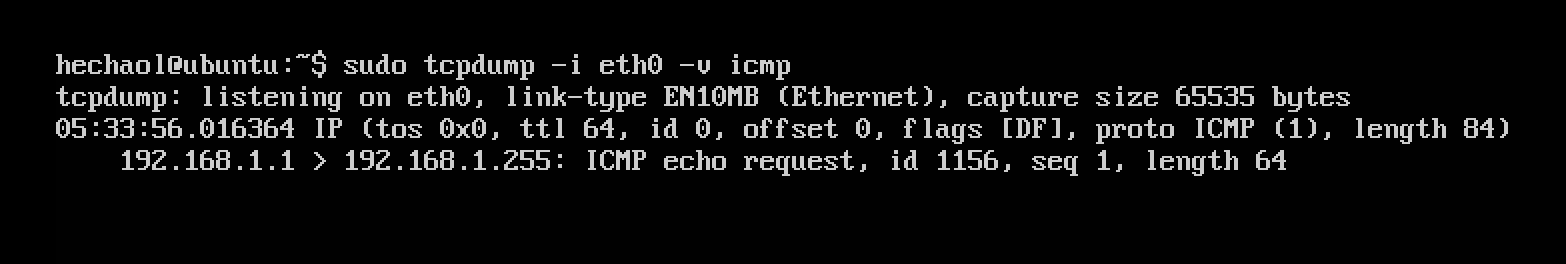
Run tcpdump on Host B:
$ sudo tcpdump -i eth0 -v icmp
On Host A, ping a broadcast address:
$ sudo ping -c 1 -b 192.168.1.255
On Host B, we will see one ICMP packet captured.
Step 4
Then we enable the second link between bridge A and B:
$ sudo ifconfig portA_1 up
$ sudo ifconfig portB_1 up
Repeat Step 3. This time we should be able to see a broadcast storm on Host B:
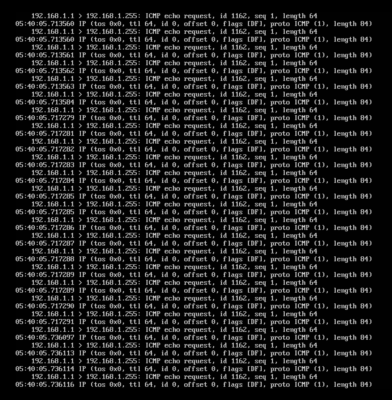
The storm will keep flooding your screen until you break one link by:
$ sudo ifconfig portA_1 down
Mac Address Learning Confusion
Due to the broadcast storm, the bridge will also be confused by the MAC
addresses. Specifically, when the first time Bridge A port 2 receives a packet
from Host A, it adds one entry Host A MAC - port 2 to its MAC table. However,
later, due to the loop, the same broadcast packet is received by Bridge A port
0, causing Bridge A to update existing entry to Host A MAC - port 0. Then the
same broadcast packet is received by Bridge A port 1, making existing entry be
updated again. So on and so forth. The bridge will keep updating the MAC table,
which is also a problem.
Spanning Tree Protocol
In above experiment, when we saw a broadcast storm, we stopped it by manually breaking one link in the loop. Rather than doing this, if we just enable STP on the bridges, the loop can also be logically broken.
To enable STP:
$ sudo brctl stp bridgeA on
$ sudo brctl stp bridgeB on
Add back the second link:
$ sudo ifconfig portA_1 up
$ sudo ifconfig portB_1 up
If now we repeat Step 4 above, we won’t see previous storm any more even with two links between bridges.
The way that STP makes the topology logically loop-free is by putting certain ports into blocking state. When there are configuration changes or bridge/link failures, STP can also detect the changes and update the topology accordingly. We will see how it works in the following sections. Only the basic idea and high level overview will be covered. For more detailed information, see RFC 7727.
Terminology
Bridge Roles
There are two bridge roles: root bridge and designated bridge.
-
Root Bridge
As the name implies, Spanning Tree Protocol generates a logical tree (which is by definition loop-free) from a topology. Thus, there must be a root in the tree. We call a bridge a “root bridge” if it is the root of the spanning tree. -
Designated Bridge
While each tree has only one root bridge, there is one designated bridge for each LAN, which becomes the bridge all hosts and bridges on the LAN use to reach the root. [1]
Port Roles
There two port roles: root port and designated port.
-
Root Port
The port with the lowest path cost to the root bridge. -
Designated Port
The port with the lowest path cost to the root bridge on each LAN.
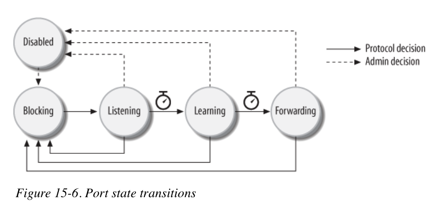
Port States
Each port can be in any of the following states:
-
Disabled
The port is shutdown through administrative action. In previous experiment, after running commandifconfig portA_1 down, the port is disabled. -
Blocking
The port is up but it doesn’t forward any traffic. In other words, it is logically shutdown. -
Listening
The port is not forwarding traffic and not learning MAC addresses. This is a transient state between blocking and learning. -
Learning
The port is not forwarding traffic but is learning MAC addresses. This is a transient state between listening and forwarding. -
Forwarding
The port is receiving and sending traffic as normal.
Port State Transition:
 (Image Credit [1])
Bridge Protocol Data Units (BPDUs)
BPDUs are protocol frames used to exchange information among bridges. There are two types of BPDUs:
-
Configuration BPDU
Used to define a loop-free topology. One important component of a configuration BPDU is priority vector, consisting of Root Bridge ID, Root Path Cost, Bridge ID, and Port ID. I will refer it as[BR-Root, Cost, BR-ID, Port-ID]. We will see how it is used later. For now, we only need to know that smaller vector has higher priority. For example, [1, 0, 1, 0] has higher priority than [2, 0, 2, 0] and [1, 0, 1, 1] has higher priority than [1, 0, 1, 2]. -
Topology Change Notification (TCN) BPDU
Used by a bridge to notify the root bridge about a detected topology change. I will not cover the topology change part in this article.
Algorithm Overview
The distributed STP algorithm consists the following steps:
- Select a root bridge and put all its ports into forwarding state.
- Each bridge selects a root port.
- Each LAN selects a designated port.
- Put all other ports into blocking state.
Root Bridge Selection
Initially, all bridges think itself is a root bridge. Thus, each of them start transmitting a BPDU with Root Bridge ID to be its own ID and Root Path Cost to be 0. Eventually, the bridge with the smallest Bridge-ID will become the root bridge. Bridge-ID format is as follows:
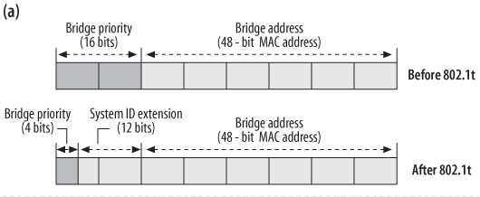
(Image Credit [1])
That means, if all bridges have the same priority, then the one with the smallest MAC address will win. However, if the administrator wants to configure a specific bridge as the root bridge, he just needs to make its bridge priority smaller than others.
Root Port Selection
After selecting a global root bridge, other bridges must select their own root port, which is the port with the shortest path to the root bridge. Note, the root bridge doesn’t have a root port while non-root bridges have one and only one root port.
Similar to selecting a root bridge, the selection of root port is also done by comparing priority vectors. On a bridge, if all ports have the same cost to root bridge, then the port with the smallest Port-ID will be selected as root port. For example, in the topology above, suppose Bridge A is the root bridge, then both port 0 and port 1 on Bridge B have the same cost to root bridge. In this case, port 0 becomes the root port because it has a smaller port ID.
Designated Port Selection
Each bridge is usually on more than one LAN, so it must learn the designated port for each LAN. As mentioned before, the designated port should be the one that has the shortest path to the root bridge and there is exactly one designated port per LAN.
Thus, for all ports on a LAN, the one with the shortest path to root bridge is selected as the designated port. If two port has the same cost, again, the one with a smaller priority vector will win.
Block All Other Ports
All ports other than root port and designated port will be put into blocking state.
Example & Experiment
Topology
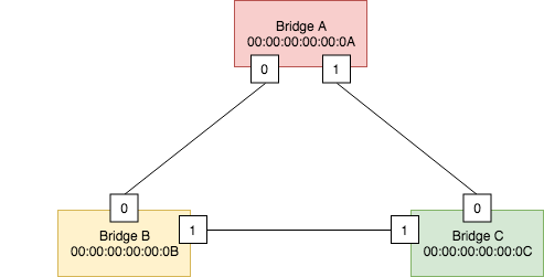
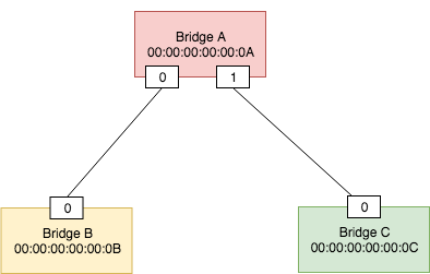
We use the following topology as an example:
First let’s add three bridges:
$ sudo brctl addbr bridgeA
$ sudo brctl stp bridgeA on
$ sudo ifconfig bridgeA hw ether 00:00:00:00:00:0A up
$
$ sudo brctl addbr bridgeB
$ sudo brctl stp bridgeB on
$ sudo ifconfig bridgeB hw ether 00:00:00:00:00:0B up
$
$ sudo brctl addbr bridgeC
$ sudo brctl stp bridgeC on
$ sudo ifconfig bridgeC hw ether 00:00:00:00:00:0C up
Root Bridge Selection
Now, let’s add the first link: portA_0 - portB_0
$ sudo ip link add portA_0 type veth peer name portB_0
$ sudo brctl addif bridgeA portA_0
$ sudo brctl addif bridgeB portB_0
$ sudo ifconfig portA_0 hw ether 00:00:00:00:00:A0 up
$ sudo ifconfig portB_0 hw ether 00:00:00:00:00:B0 up
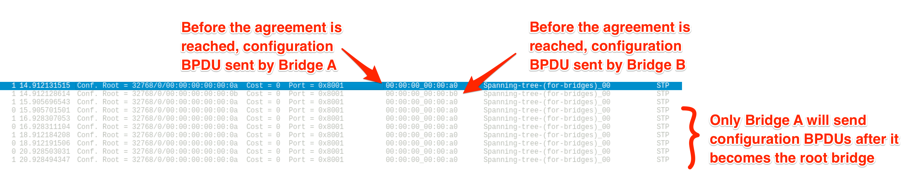
After we enable both ports, we will see BPDUs exchanged by bridge A and B.
- Both bridges send a BPDU with their own Bridge-ID as Root Bridge ID.
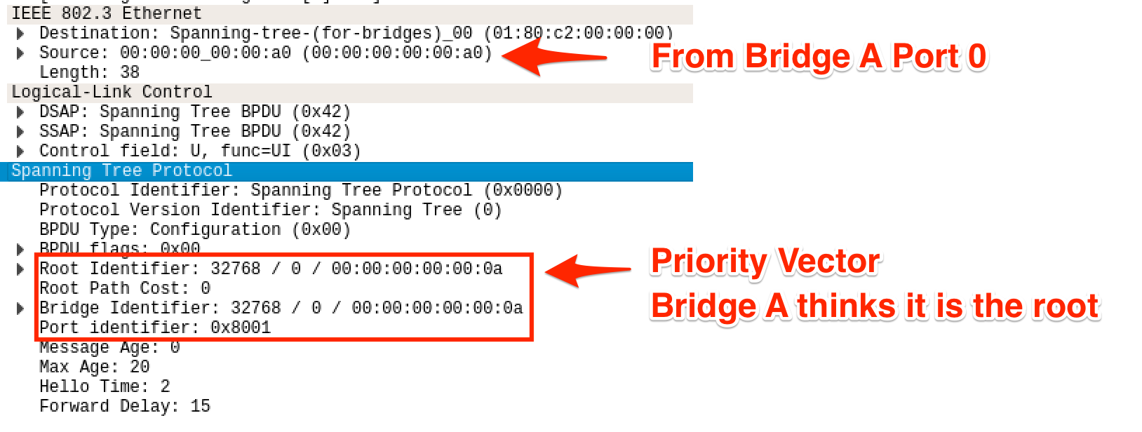
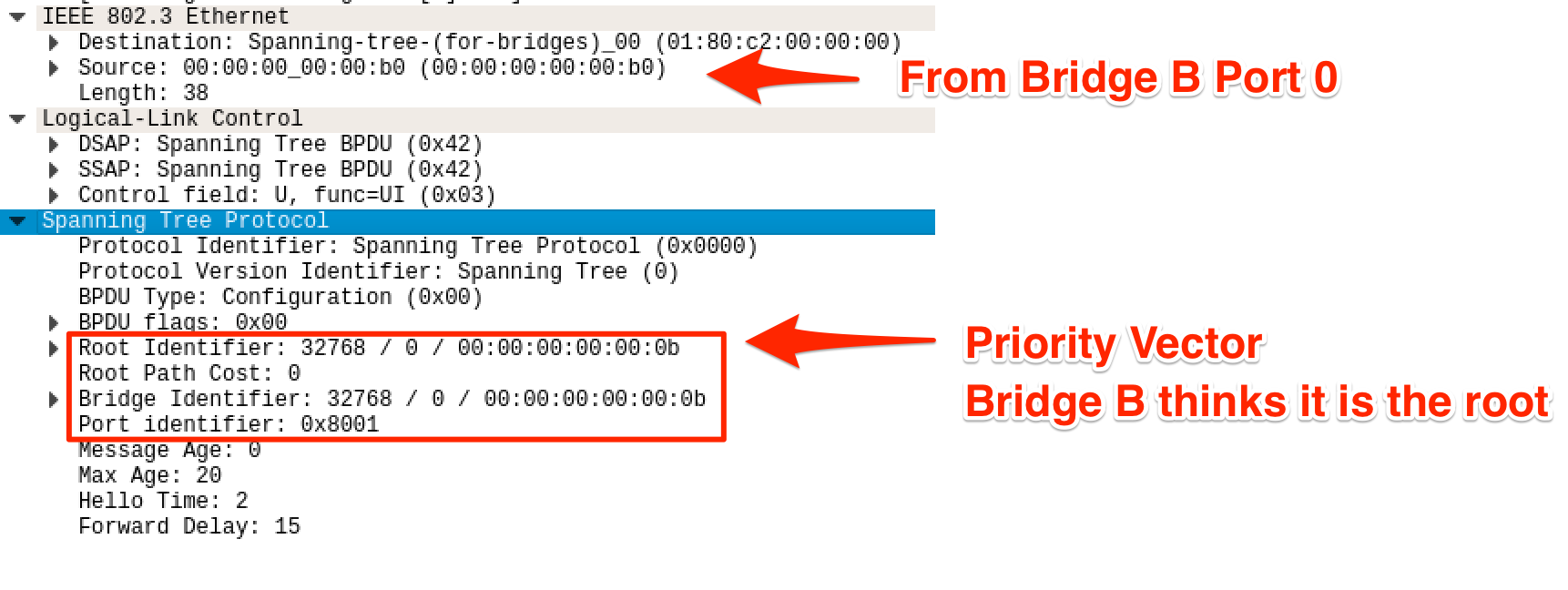
- Bridge A and B agree that A is the root because it has a smaller priority vector (smaller Bridge-ID). After this agreement is reached, only Bridge A will send BPDUs.
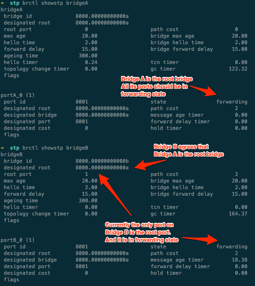
Current bridge and port info:
Next we add one more link portB_1 - portC_1.
$ sudo ip link add portB_1 type veth peer name portC_1
$ sudo brctl addif bridgeB portB_1
$ sudo brctl addif bridgeC portC_1
$ sudo ifconfig portB_1 hw ether 00:00:00:00:00:B1 up
$ sudo ifconfig portC_1 hw ether 00:00:00:00:00:C1 up
After Bridge C is connected to Bridge B through portC_1, it first thinks
itself is the root bridge and sends a configuration BPDU with its own Bridge-ID
as the Root Bridge ID.
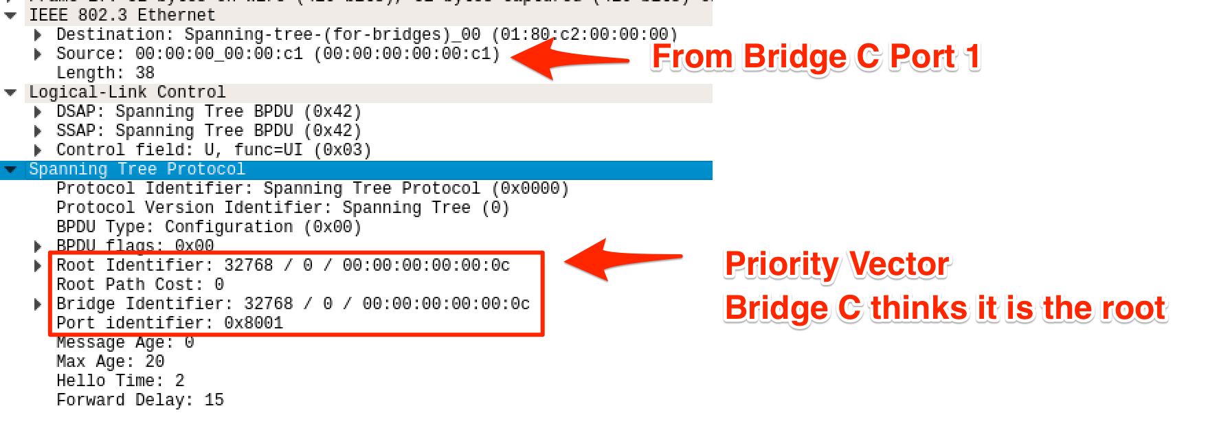
Then after it receives a BPDU from Bridge B, saying that the root bridge is A, Bridge C will agree on that and stop sending BPDUs.
Bridge C’s info:
Root Port Selection
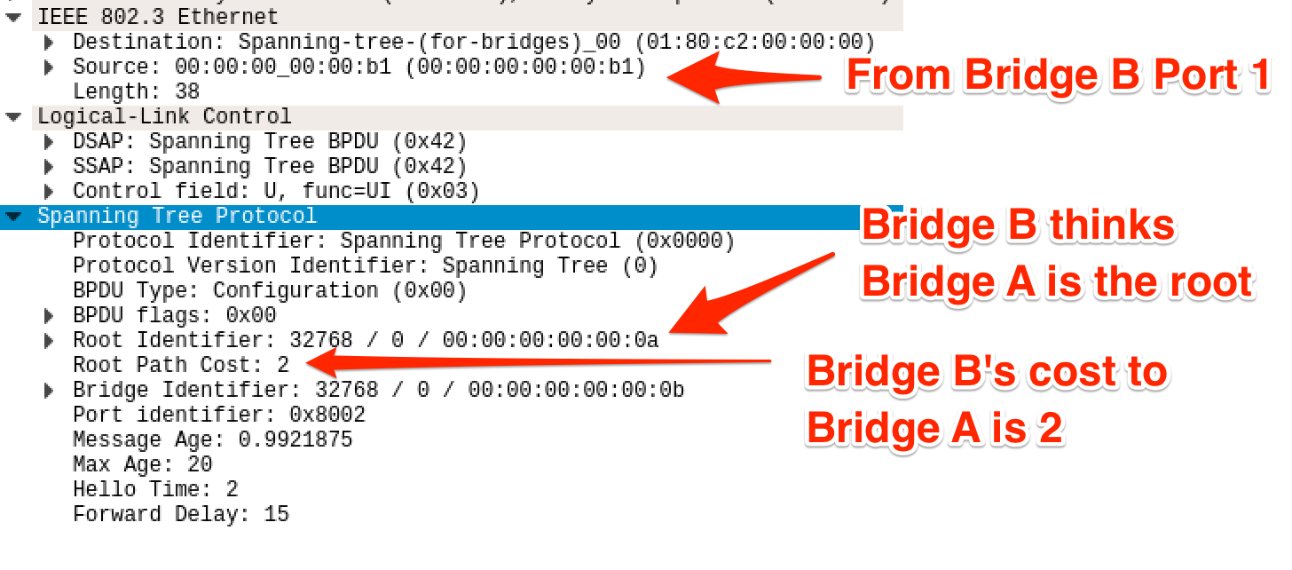
Now we add link portA_1 - portC_0. After that, there will be a loop in this
topology. In theory, this time portC_0 should become the new root port of
Bridge C because it is closer to root bridge A (cost 2) comparing to portC_1
(cost 4).
$ sudo ip link add portA_1 type veth peer name portC_0
$ sudo brctl addif bridgeA portA_1
$ sudo brctl addif bridgeC portC_0
$ sudo ifconfig portA_1 hw ether 00:00:00:00:00:A1 up
$ sudo ifconfig portC_0 hw ether 00:00:00:00:00:C0 up
Let’s see what happens after adding this link.
Topology Change Notification (TCN) BPDUs will be sent first. But I will skip this part and only focus on how it reaches a loop-free topology.
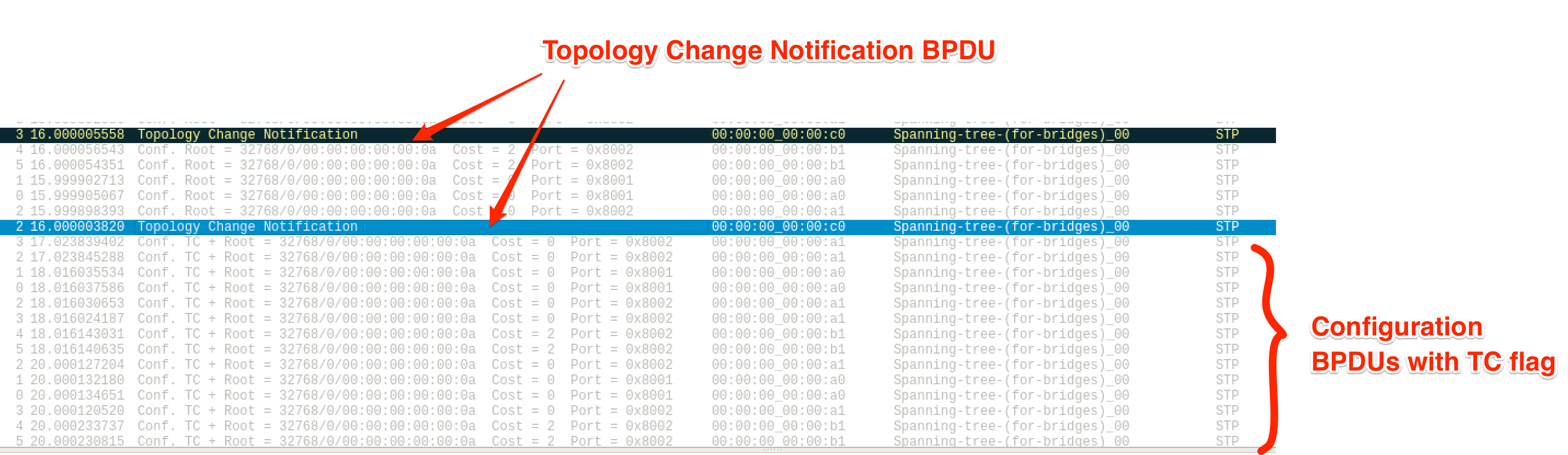
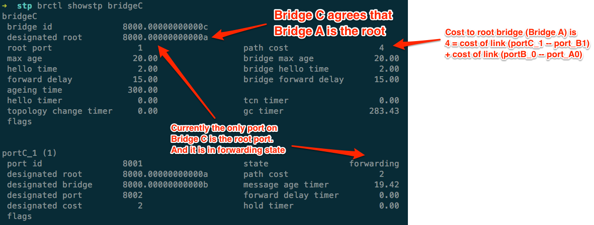
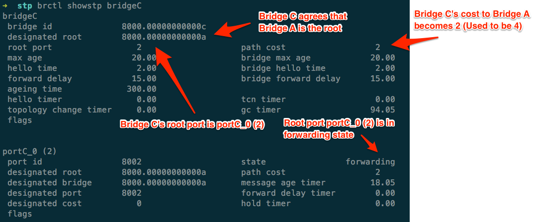
Bridge C portC_0 should receive BPDUs with Root Path Cost 0 sent by Bridge A
portA_1 and calculate the cost of portC_0 to root bridge A, which is 0
(Root Path Cost in BPDU) + 2 (port cost) = 2. Since its cost to root bridge is
less than portC_1, portC_0 now becomes the root port. This can be verified
looking into the bridge info:
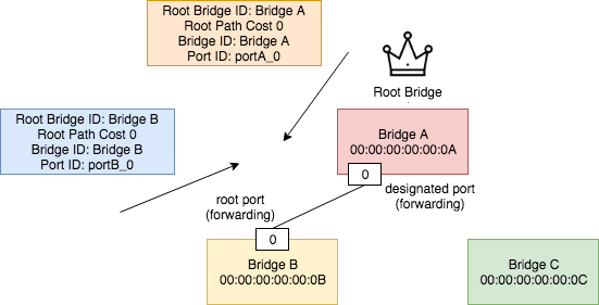
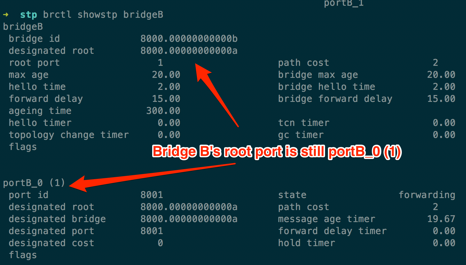
The root port of Bridge B stays unchanged and it is still portB_0.
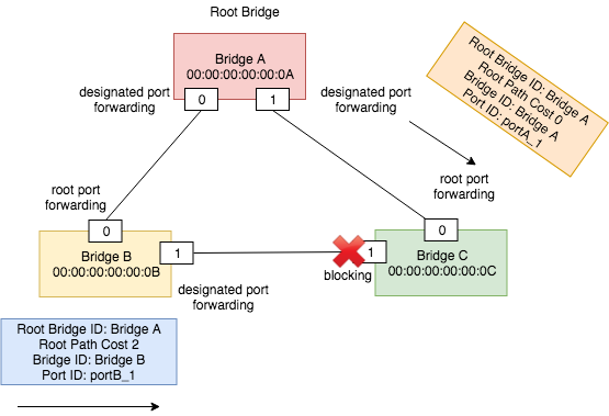
Designated Port Selection
There are 3 LANs in the topology: link portA_0 - portB_0, link portA_1 -
portC_0 and link portB_1 - portC1. For the first two LANs, the designated
ports are no doubt portA_0 and portA_1 because they are the ports of root
bridge. For LAN portB_1 - portC1, they need to select a designated port. As we
can see, both ports have same cost to root bridge. But since Bridge B has a
smaller Bridge-ID, portB_1 becomes the designated port.
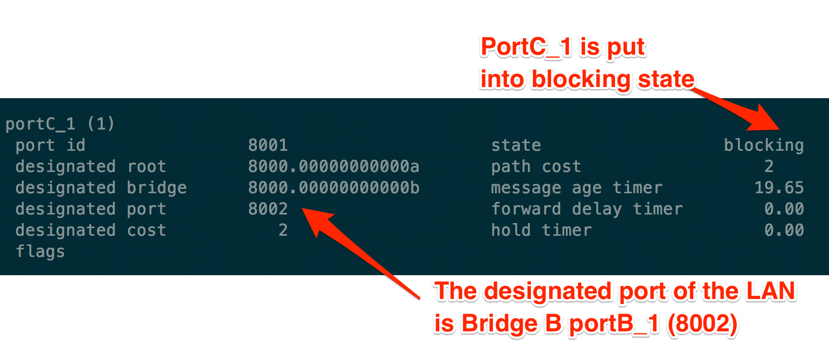
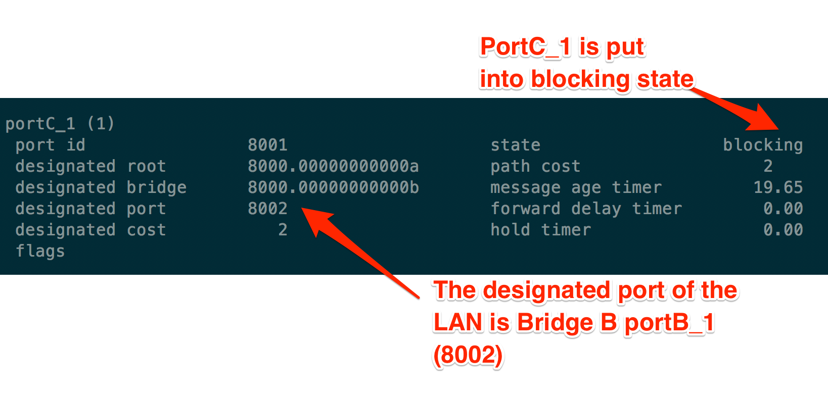
Block All Other Ports
portC_1 is not selected as the designated port in LAN portB_1 - portC_1, nor
is it the root port of Bridge C. Thus, it is put into blocking state.
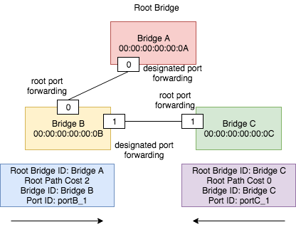
Now the topology is loop-free. Logically, it looks like:
If we shut down portB_0, then STP will detect the topology change and
re-enable portC_1. I will leave this experiment to the reader.
Reference
[1] Benvenuti, Christian. Understanding Linux network internals. “O’Reilly
Media, Inc.””, 2006.
[2] BRIDGE 8